How we scaled our terrain across the globe using 3D tiles
.webp)
Sensat's Senior Software Engineer, Chris Kapp breaks down how Sensat's team has scaled terrain across the globe using 3D tiles.
Introducing 3D tiles
3D tiles are the latest engineering craze in the geospatial world, and it’s easy to see why. They provide a simple method for different types of 3D geospatial data to be integrated and rendered together. We’ve been using them to power our world-class 3D geospatial renderer and it’s helped us to continue pushing the boundaries of what’s possible in a web browser.
3D tiles work brilliantly for small-to-medium sized data sets, but we came across some interesting challenges when scaling to really big data sets. This article recounts how we scaled a single tileset containing terrain data spanning the globe with over 33 million tiles and that reference over 6 Terabytes of content, and how we utilise that data in our WebGL-based renderer.
Why did we need a tileset this big, and why terrain?
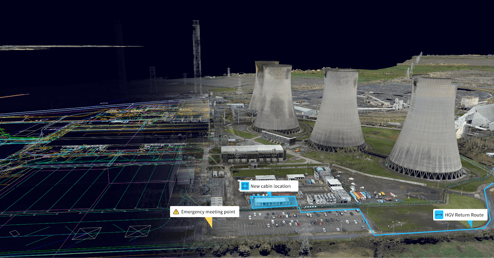
At Sensat we’ve invested heavily in 3D tiles, utilising the loaders.gl library to provide an entry point for our custom three.js-based renderer to visualise a wide variety of different data sets including BIM, CAD, Photogrammetry, and point clouds. It’s the format we’ve centralised on for storing and indexing all our 3D data and in the interest of minimising our renderer’s complexity, we want to keep it that way.
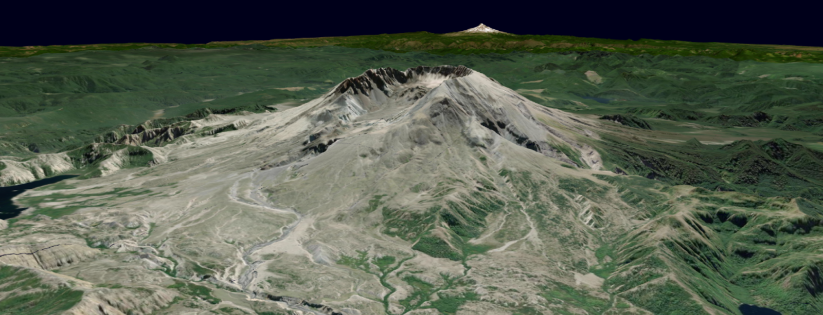
Our core product revolves around reducing risk and improving decision-making in construction projects by visualising all of your data contextually in one centralised view. The majority of our customers will have photogrammetry scans of their project area that form the basis of a digital twin. However, these scans can be expensive and limited in scope and we wanted to provide users with a baseline terrain model which could be used to cover areas that hadn’t been scanned.
Given that, you may wonder why we didn’t opt to integrate with Google’s photorealistic tiles, which are also delivered as a 3D Tiles tileset. Unfortunately, this is a DSM (Digital Surface Model) rather than a DTM (Digital Terrain Model) which means it also contains all the buildings and trees which could conflict with a project needing to demolish existing buildings in order to start.
A tale of two parts
This project presented us with two main challenges involving scalability:
- By default when a tileset gets sufficiently large, 33 million tiles large in our case, it requires a tileset.json file hundreds of megabytes in size. This is a problem because this is all the metadata we need to determine what’s visible on screen. Without that metadata, we can’t even start trying to request the content - let alone render anything on screen.
- Even if we got the metadata to the browser, how would we parse a tree containing 33 million nodes without exhausting the browser’s resources?
Part one: Getting the data to the browser
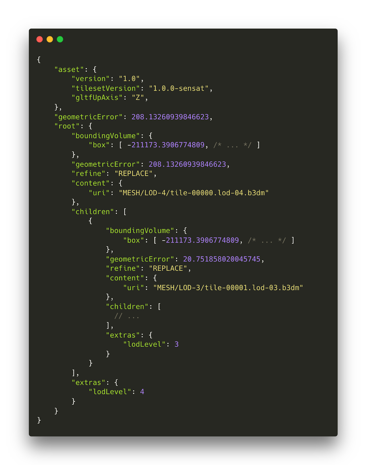
If we wanted to generate a standard tileset.json, it’d look something like the following. As it stands, that’s going to be far too much data to send to the browser. But we’re not out of luck!
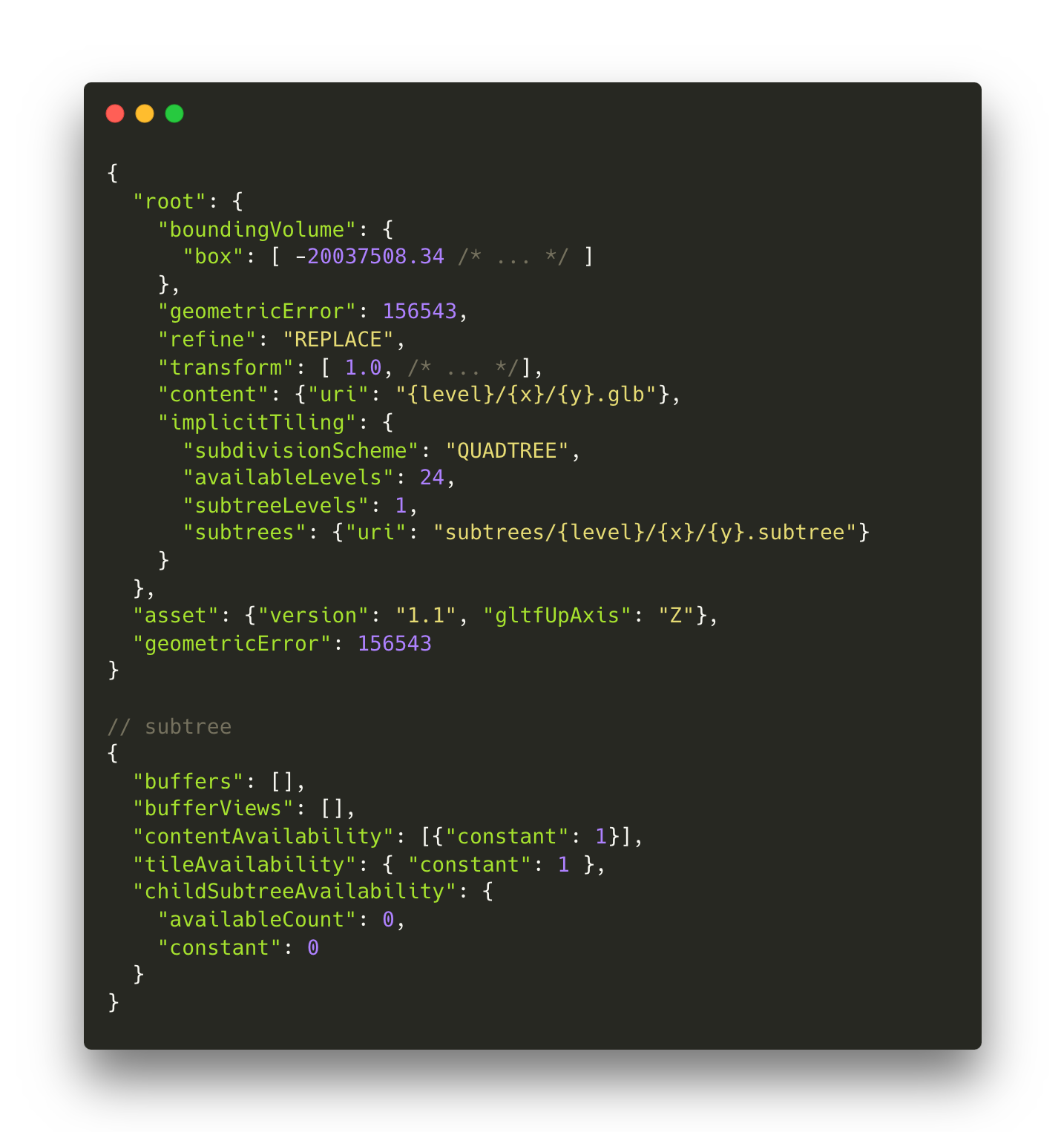
Instead, we can utilise the version 1.1 ‘Implicit Tiling’ feature which defines each level of detail as being split in half on each applicable dimension. For a quadtree like our terrain, we’ll end up with four child nodes for each node, in a tiling scheme that is very similar to XYZ tiles.
Implicit Tiling uses an additional piece of metadata called subtrees. These subtrees are a collection of files describing which tiles within the tree are available and subsequently which of those tiles have content. Subsequently, each subtree contains up to two bitstreams arranged in a morton index pattern to store that data. If we were to try to encode the availability information for our terrain tileset, that would still be at least 66 million bits of data. We’re doing better, but this is still too much data to send over the network.
Fortunately for us, our terrain is modelled in EPSG:3857 which is defined for almost the entire globe and the area for which it is defined doesn’t contain any holes. This is particularly convenient as it means that we can replace the bitstreams with a constant value of 1 and avoid sending the bitstreams altogether. With these tweaks, we’ve reduced our hundreds of megabytes of metadata down to a single piece of JSON of just a few hundred bytes.
Part two: Traversing 33 million tiles in the browser
Now we’ve got the tileset in the browser, we’ve got to tackle how to determine what to render. Typically, we’d traverse the tileset in the following manner, similar to an existing implementation like loaders.gl.
Initially, we’d select all of the root-level tiles that make up a model, then for each tile we’d project the geometric error to screen-space error using the tile’s centre to find how many pixels of error there are for a given geometric error at that distance
While this approach works nicely for simple tilesets, it’s not going to scale to the number of tiles we’ll have in our tileset.
We wondered if it would be possible to do something similar to a more traditional 2D XYZ tile selection, which would mean finding the tiles within the camera’s viewing frustum rather than matching the tiles to the camera’s view.
Our starting premise was: Given that the implicit tiles standard enforces the geometric error changes predictably and monotonically, could we use an allowable geometric error to calculate an allowable LOD? Since screen-space error is our metric for determining what to render and it’s derived from a combination of geometric error and distance to the camera, there should exist some function which defines geometric error over the camera’s view frustum. With that function, we could determine the geometric error at any given position to know which LOD needed to be rendered.
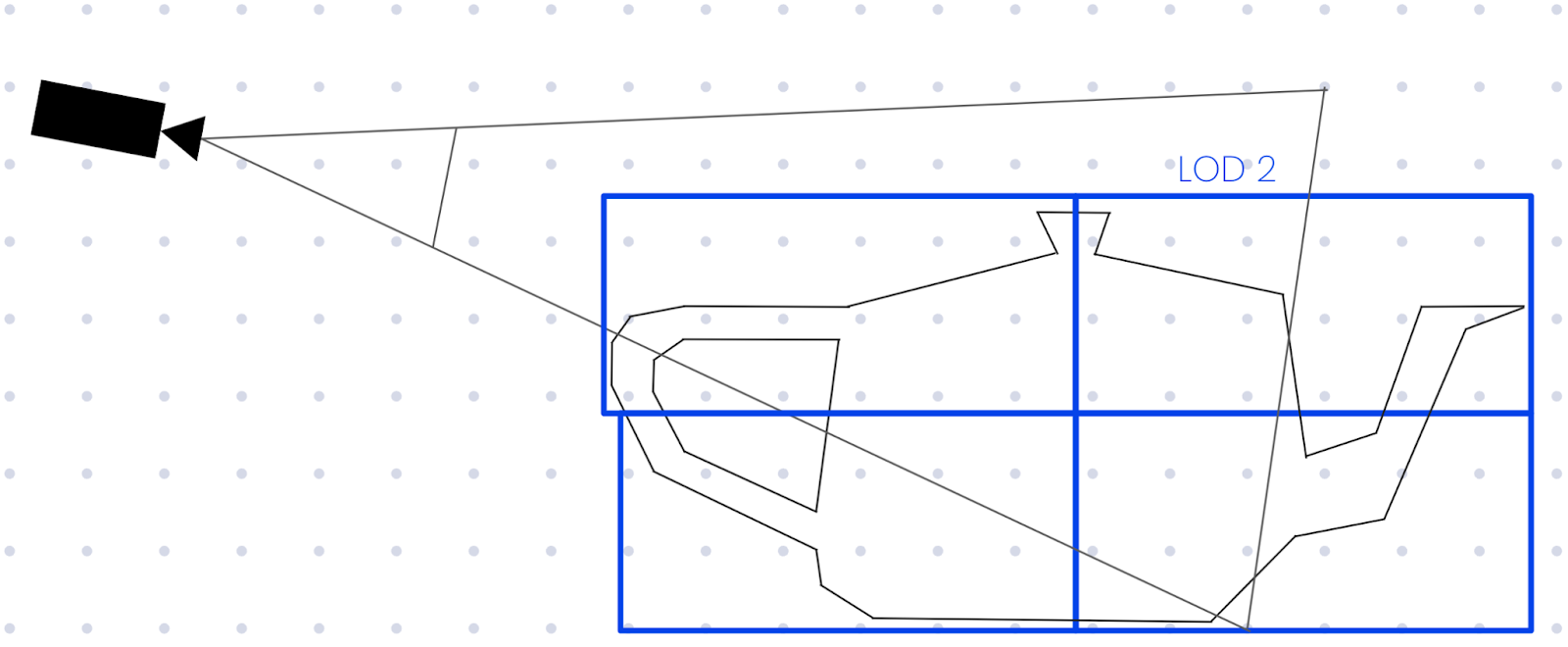
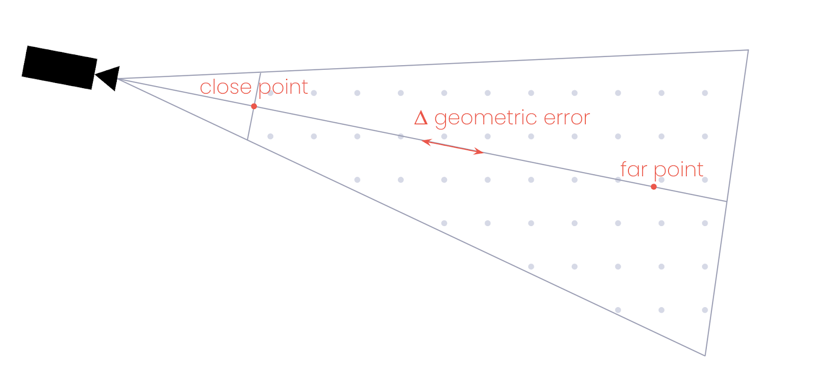
Such a function could be calculated, but like many computer graphics techniques, we just need an approximation that is good enough that it becomes indistinguishable from correctness. First, we use the camera’s forward vector to project a point on the camera’s near plane and a point further out in space. At each of these points, we can derive the geometric error and use them to approximate the change in geometric error as we move along the camera’s forward vector.
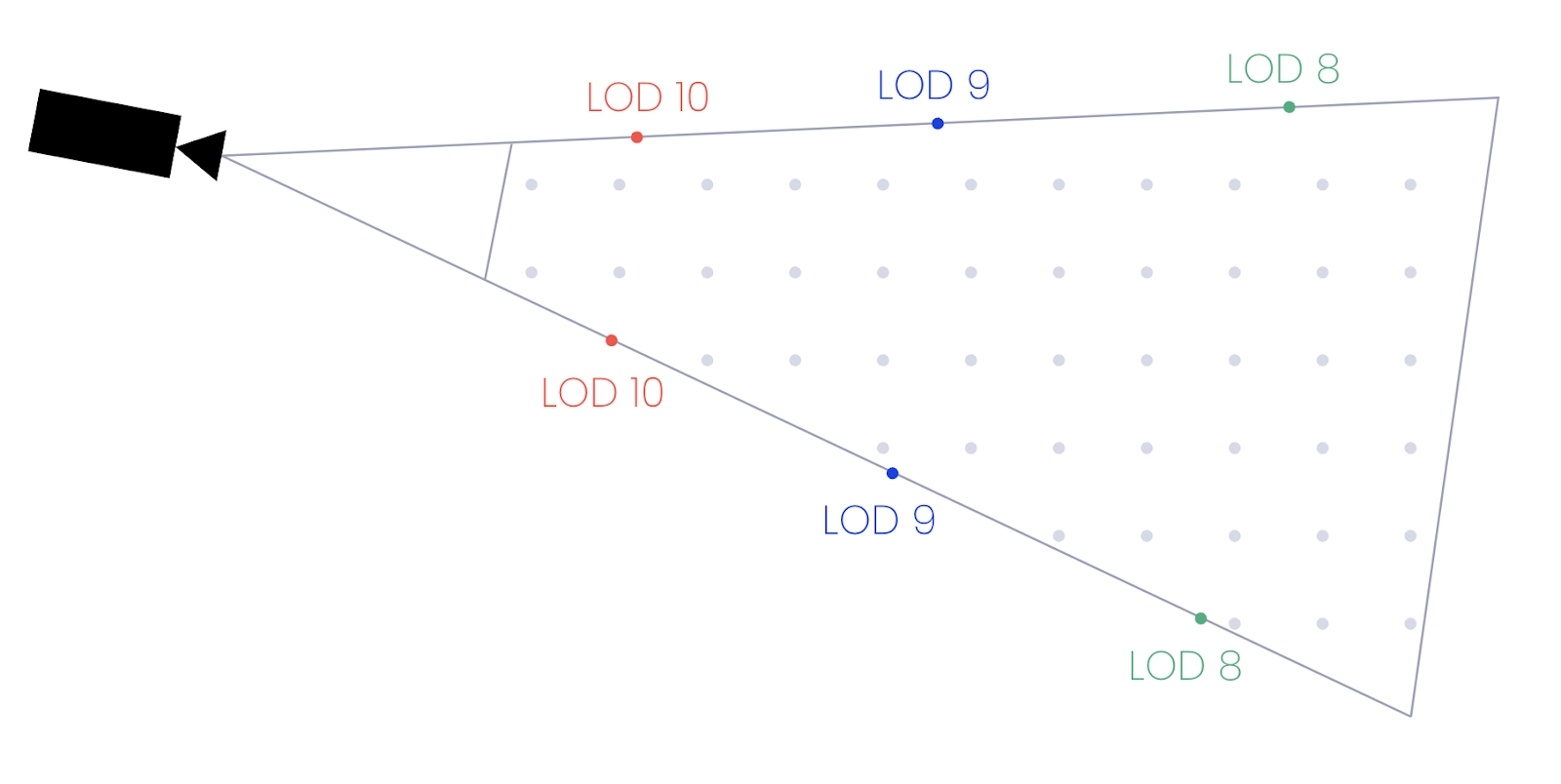
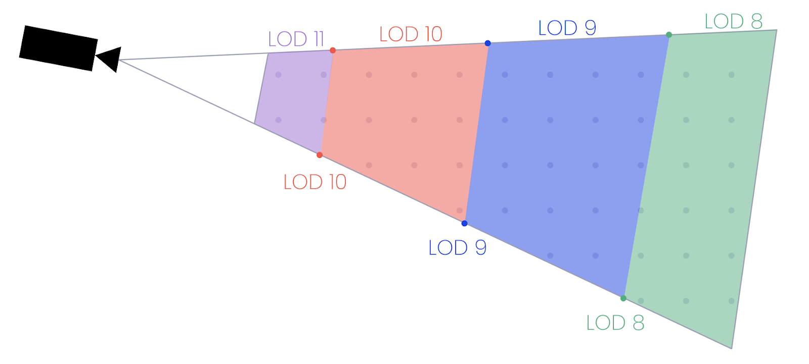
As we have a change in geometric error per unit distance, we can calculate the distance from the camera for each point where the acceptable LOD changes from one level to the next. For each distance value, we can travel that far along each of the four corners of the camera’s frustum (top left, bottom left, top right, and bottom right corners of the screen) to generate a set of points that define the boundaries where the LOD needs to change.
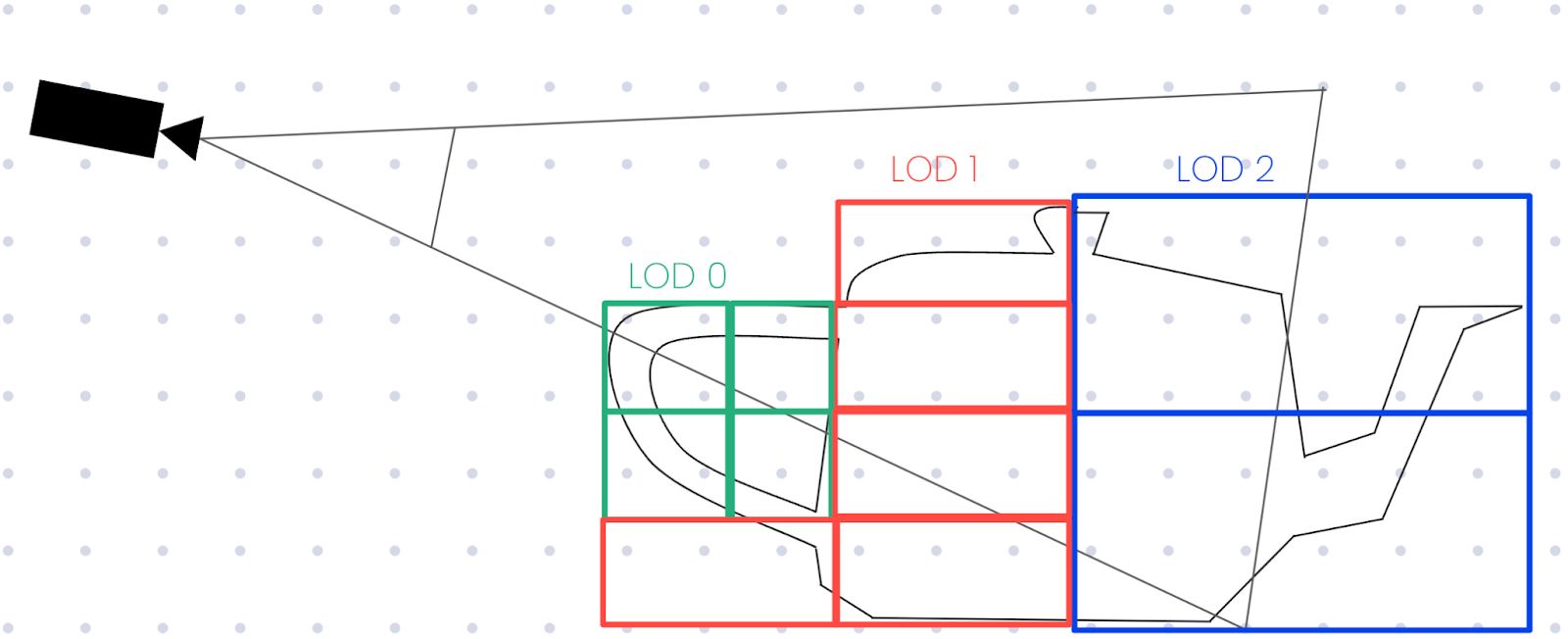
With these boundary points, we can generate an approximate bounding box where we know which LOD must be selected.
Again, due to the constraints of the implicit tiling schema, we can calculate the exact size of each tile based on the LOD to determine which tile(s) are within the bounding area. With a list of tiles that overlap with the bounding areas, we might have something that looks like the following.
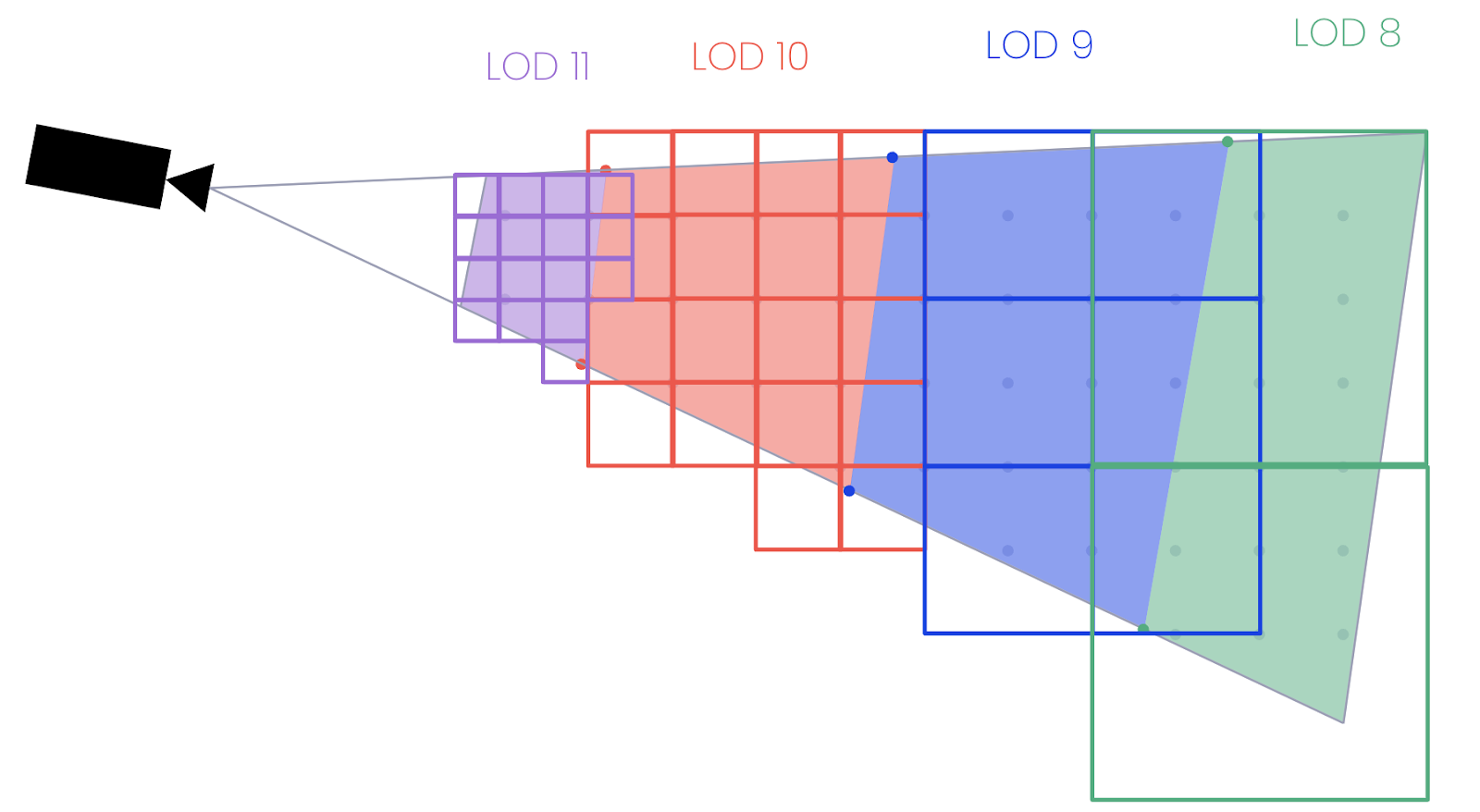
This is actually pretty close to our final result, although we can see that there are a few places where tiles from different LODs (such as 10 and 11) are overlapping. If our 3D tileset used the ADD refinement strategy it wouldn’t matter, but since these terrain tiles are meshes we’re using a REPLACE strategy where we should only be rendering one tile in each position. We can opt to fix this one of two ways:
- Remove overlapping tiles where the parent is also in the selection, which brings the boundaries closer to the camera. Doing so would improve performance, but reduce quality as we’re rendering less detail and we might exceed our allowable screen-space error metric.
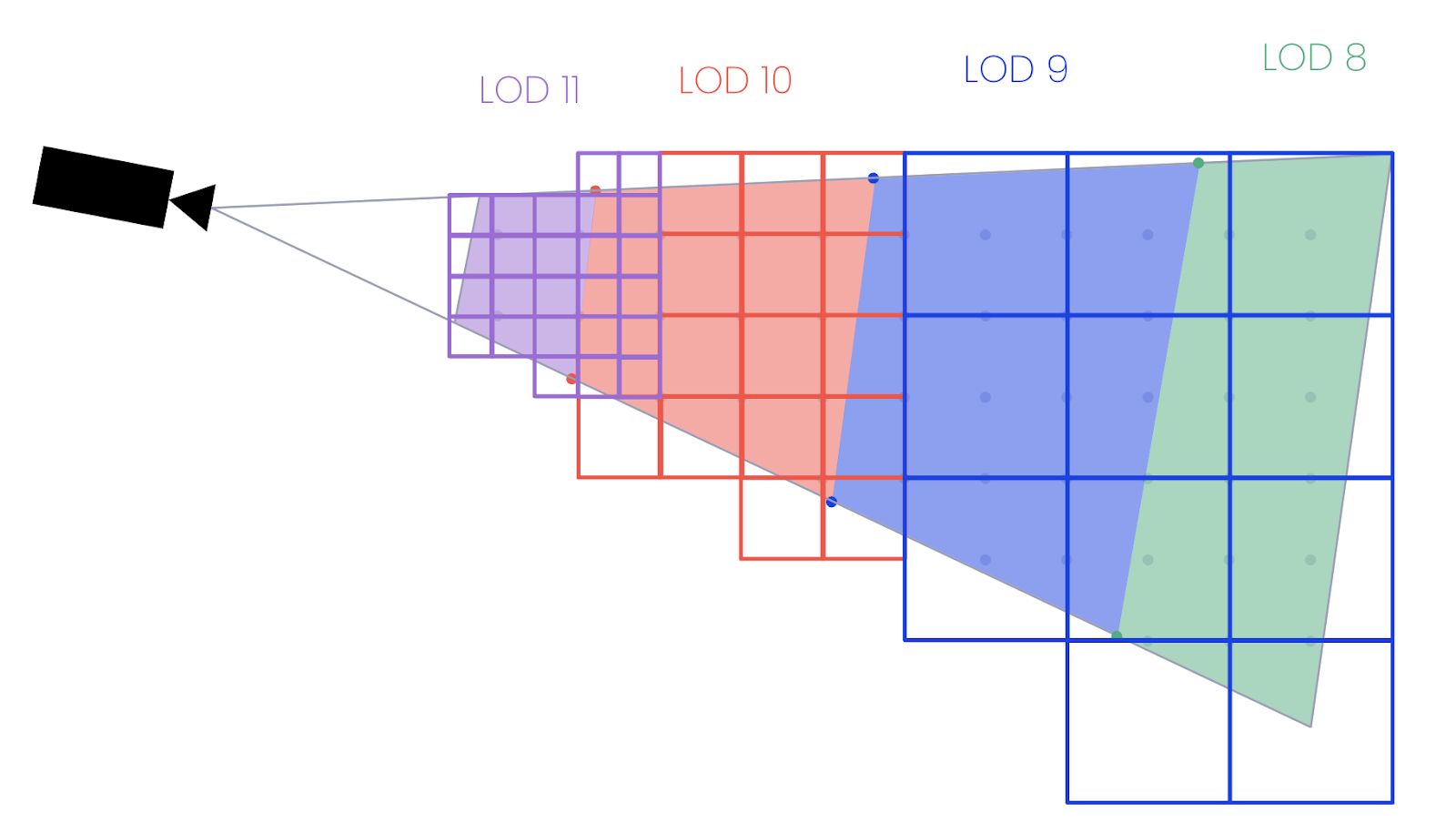
- Remove the parent tiles of overlapping tiles and replace them with a set of child tiles at the appropriate LOD. Doing so would result in a better quality image, but increased frame times. It has the same effect as moving the tile boundaries slightly further away from the camera.
In our case, we want to optimise for rendering quality where possible, so we chose to implement option 2 which ensures that our maximum allowable screen-space error is never exceeded and users should not be able to perceive when we substitute a tile with a lower level of detail.
The final result
Putting it all together, we can now use our new tileset with our new tile selection to fetch and render just the data we need, and nothing more. We’re also able to run our algorithm in a matter of a few milliseconds, much faster than we could have traversed a potentially large subset of the 33 million tiles referenced by the tileset.